B1B Wiring Harness Diagram Notes From David Erb (revised Nov, 2008)
IMPORTANT – It is strongly suggested that before you embark on building your own Pilothouse wire harness you read all these instructions first. It will save you lots of time in completing this project.
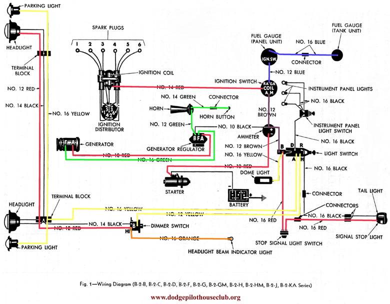
This harness is very easy to build. I made mine in about four hours. It is inexpensive to make. The terminal ends and bullet connectors actually cost more than the wire. The B1B circuitry for the electric system is very basic, and consists of only about 30 separate pieces of wire. The electrical schematic for the circuits can be found in the shop manual and in the Dodge Pilothouse website archival information.
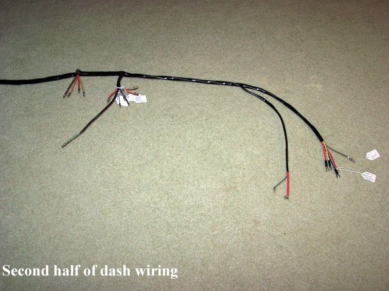
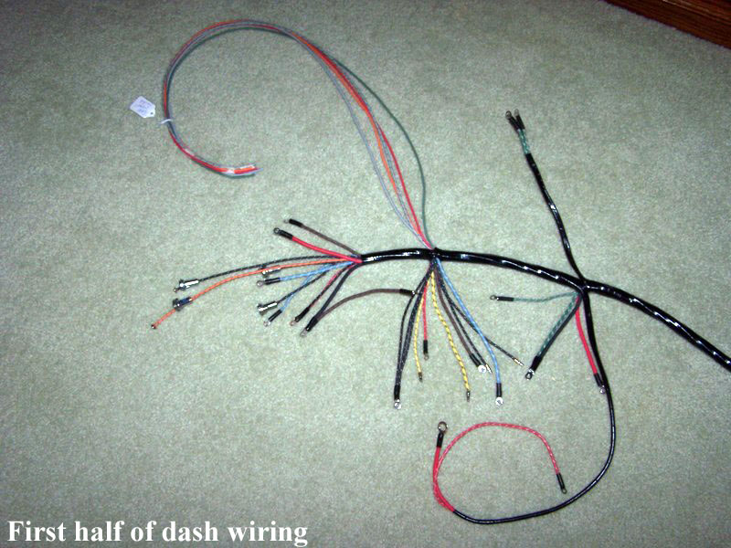
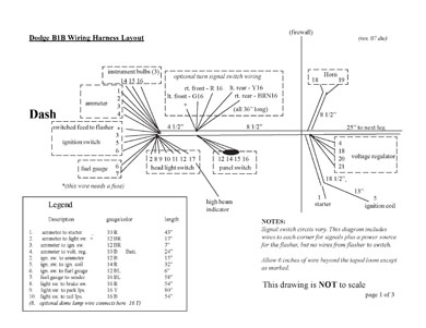
The dimensions for the harness wires in the drawing provided are from factory harness, and will work. Having said that, these dimensions are JUST long enough to work, and allow for no room to work while installing the harness. Since this harness must be pulled into the firewall from the engine side, I strongly suggest that you add an extra twelve inches to each wire that connects to the dash gauges and switches. This gives you extra room to make each connection with much more ease. If you have fresh paint on your dashboard, it will also allow you to wire the dash gauge unit without skinning up the fresh finish.
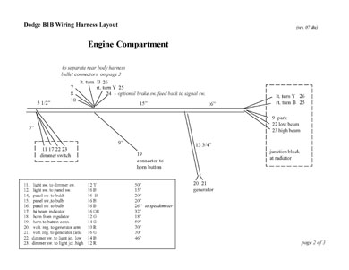
There are four very short wires you need to note when building this harness. Wire number 2 connects the light switch to the ammeter. Wire number 3 runs from the ammeter to the ignition switch. Wire number 6 connects the fuel gauge to the ignition switch. Another very short wire connects the headlight switch to the panel switch, (They are next to each other on the dash panel.), number 12 in the detail on page 1. The drawing shows these three short wires wrapped into the harness, but this is optional and is not necessary. All these components sit in the dash within a few inches of each other.
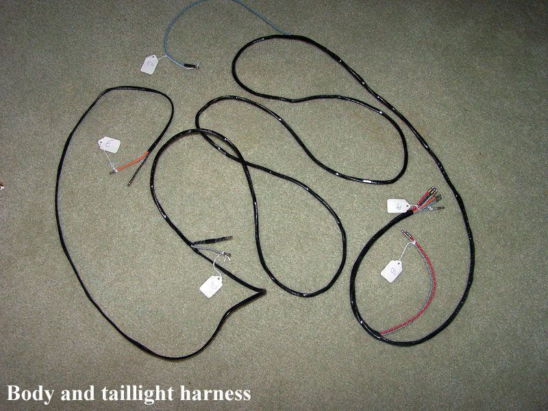
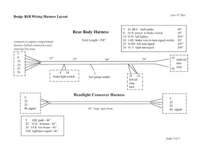
Page 1 and 2 of the drawings show the Main Harness that serves the dash and engine compartment. Page 3 illustrates the Rear Body Harness. You need weatherproof bullet-type connectors to join the two harnesses professionally. They are near the steering box area. You will also need similar connectors to join the tail and park lights to their harnesses. Without turn signals you will need nine of these connectors. Turn signals will require an additional five connectors.
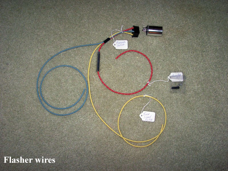
I have shown the Rear Body Harness drawing as the correct arrangement for applications where turn signals are used, on page 3. If you are not using turn signals, you do not need wires number 25 and 26. Just run wire number 24 from the brake light switch back to each tail light for the brake lights. Likewise, on the page 1 drawing you may eliminate all the optional wires shown for the turn signal switch application.
When you build your harness, it is helpful to first make number labels for each wire. I used a computer mail label maker. You can alternately buy a few sheets of labels and use these to number each wire at both ends before you wrap it into the harness with tape. If you follow this practice, you will never have to get out the ohmmeter to find which wires go where. Ask me how I know . . . . . .
I found that when wrapping the loom, it works best to wrap a rag around one end and pinch it in a vise. Then get a helper to hold the assembly taunt while you wrap it with tape. Best to use a good quality vinyl tape product here – this is not a logical place to scrimp. Optionally, you may wish to use vinyl covering over your taped harness after it is finished. Several products and colors are available.
Build the complete harness before you install the terminal ends. These can be put on after the assembly is completed. I suggest using uninsulated terminals that are soldered and insulated with heat shrink tubing. This method is superior to using crimped terminals. I found uninsulated terminals, wire and harness connectors at Sherco Auto Supply, Margate, FL, 954-975-0012 or at www.sherco-auto.com. They also carry the weatherproof bullet connectors necessary to join the rear body harness to the main loom and for connecting tail and parking lights to their respective looms. Their prices are very reasonable.
On the subject of connectors, if you use your stock switches, you will need round male bullet connectors for the headlight and horn switches, as well as the brake light switch. Most other wires use eyelet connectors. The power supply wire to the headlight switch from the ammeter uses an eyelet, as does the wire at the headlight switch that feeds the brake light switch. I recommend strongly that you avoid at all costs any aluminum terminal ends. These are just too soft, and will break off with a very slight pull on the wire. Steel terminals are far better.
Wal-Mart sells a refillable pocket torch for $12 that uses butane lighter fuel. It is just a little larger than a disposable lighter, and is instant on-off. This is the perfect tool to use for heat shrink tubing and soldering. Please don’t use it under the dash – it can start fires. I have used this little pocket torch as well as a heat gun to shrink multiple pieces at one time on the work bench.
Harness Installation
When you install your new harness, it must go through the firewall from the engine side. Work it through carefully until you have the horn and regulator wires pulled up against the firewall. On the ignition switch, the tallest of the three terminals gets only one wire, while the other two terminals each have several wires on them. The factory used one nut between each wire terminal, and just stacked them up. On the panel switch, the single wire goes on the right side terminal and the three-gang connector goes on the left side, terminals facing upward in the dash.
The power supply wire from the starter to the ammeter goes on the left side of the ammeter gauge as ir sits in the dash, and the other wires go on the other terminal. If you connect the gauge wrong, it will read backwards.
Additional Notes:
Before you can disconnect or connect any dash wiring, it will be necessary to pull the gauge cluster rearward about six inches. Before this can be done you must disconnect the oil pressure gauge feed line under the hood near the firewall and the temperature gauge sender capillary tube at the driver’s side of the cylinder head at the rear. This temperature sender is very fragile and can be easily bent or kinked. If this happens, you will need to buy a new temperature gauge, and they are expensive. I recommend disconnecting the oil pressure line near the firewall and unhooking the temperature sensor from the head, then working these two leads carefully through the firewall until you can pull the dash gauge unit rearward about six inches – the distance you will need to make your new harness connections. I added a one foot extension to my oil line to make this job easier in he future.
All electrical circuits in the vehicle are sourced from the ammeter positive post (right side as it sits in the dash), so these wires are quite important. I needed to paint my dash anyhow, so I removed the entire instrument cluster. If you do this, be careful with the temp gauge lead. It is very fragile. If you nick or crimp it, it will leak out the ether gas inside, and you will need another gauge.
Use removable male type bullet connectors for connecting the tail lights to the harness, the horn wire to the steering column and the body harness to the main front harness near the steering box area (tail lights, stop light switch and fuel sender wire). This is in accordance to the original factory layout, and works out well. The only really waterproof connectors I could find were from Sherco, as mentioned above. Enough connectors for the whole job cost me $60. You need to buy separately the make and female plastic connectors, the terminal pins and weather seals for each wire separately.
The ignition switch has only three terminals. The tallest is the power feed from the starter, and should have only one wire on it. The other two posts can he used for any circuit that comes off the switch without any particular order. The two remaining posts are both “on” when the switch is turned on. There is no accessory or start position on the original switch.
The headlight switch has a circuit breaker on the front. The front terminal of the breaker is connected to the power wire from the ammeter. The second terminal on the circuit breaker (front to back) is hot all the time, and is connected to the brake light switch and dome light, if you have one. The two remaining terminals are for park lights and head/tail lights. These two wires each need a male bullet connector to fit the original switch.
If you use the original switch, the tail lights will not work with the parking lights, hut only with the headlights. This is the nature of this switch. Also, the panel lights come on only with the head lights, as opposed to newer vehicles. The right hand panel switch terminal is connected to the head light switch, and the left panel switch terminal is connected to the three dash lamps. If you want your lights to work like newer vehicles – park lamps stay on with headlights, dash and tail lights work with both park and headlights – you will have to find a newer type switch.
The dimmer switch has three terminals – one feed from the headlight switch and two wires out to the headlight junction block on the radiator support. The high beam dash indicator is connected to the high beam terminal on the dimmer switch. Look at your dimmer switch to see what kind of posts it has before you put your terminals on the harness at this point.
When you buy terminal ends, be aware that there are both steel and aluminum types available. All the cheap stuff is aluminum. The good steel types are twice as strong and unfortunately, twice as expensive. On your connectors for the ignition switch, headlight switch and ammeter, you will find the need to combine three or four wires into one terminal post. I stripped an inch of insulation from each wire, twisted these together, and soldered them into one large diameter eyelet terminal, then used heat shrink to stiffen the connection well. This makes for a very neat and compact connection. The factory method was to use one connector for each wire, and to stack them up with a nut between each terminal on the switch or gauge post – a cumbersome way to do things but it works okay.
Using modern insulated wire, heat shrink and soldered terminals, the harness you build will be safer and will last much longer than the original. Total cost for the harness I built was just over one hundred dollars.
One last hint to help make this job easier – find a good system for labeling your wires. Write or type these legibly. When you’re lying upside down under the cramped dash trying to read them, you will be glad you did. AND do use the correct colors following the shop manual schematic. It certainly makes troubleshooting easier when problems arise later on.
The logical way to get the harness fed through the firewall is to wrap all the wires together in compact fashion and then tape them together like this with blue masking tape – comes off easier than the tan stuff. If you do this over top of your labels, many of them will tear off when you unwrap them, after you have pulled the harness through the firewall hole. To keep this from happening, just wrap a plastic bag over the harness before you tape it together with masking tape. Then, once you have pulled it through, the tape will come off without removing any important labels. The hole in Pilothouse firewalls is about 1 ½ inches in diameter. Originally it had a rubber grommet on the edges to protect the wires. These are still available from restoration supply houses. Failing this, a good dollop of black silicone sealer will help keep the heat and noise out.
Good Luck
Dave Erb
New Holland, PA
oldabe@copper.net |